


Measuring Disc Brake Alignment Tolerance at Home
Understanding Disc Brake Alignment Tolerance
Disc brake alignment tolerance refers to the acceptable range in which the brake caliper, rotor, and pads can deviate from perfect alignment without causing brake rub, uneven wear, or inconsistent braking. Modern road and gravel disc systems are designed with small tolerances, especially as rotor sizes increase and frame clearances become tighter.
Measuring alignment tolerance at home helps identify whether brake noise or drag comes from setup issues, component wear, or frame and fork inconsistencies.
Why Alignment Tolerance Matters
Poor alignment does not always mean the brake is incorrectly installed. In many cases, the system may be within tolerance but close to its limits. Understanding how much margin exists helps distinguish between normal behavior and true mechanical problems.
Alignment tolerance affects brake modulation, pad life, rotor heat distribution, and long-term hub bearing load.
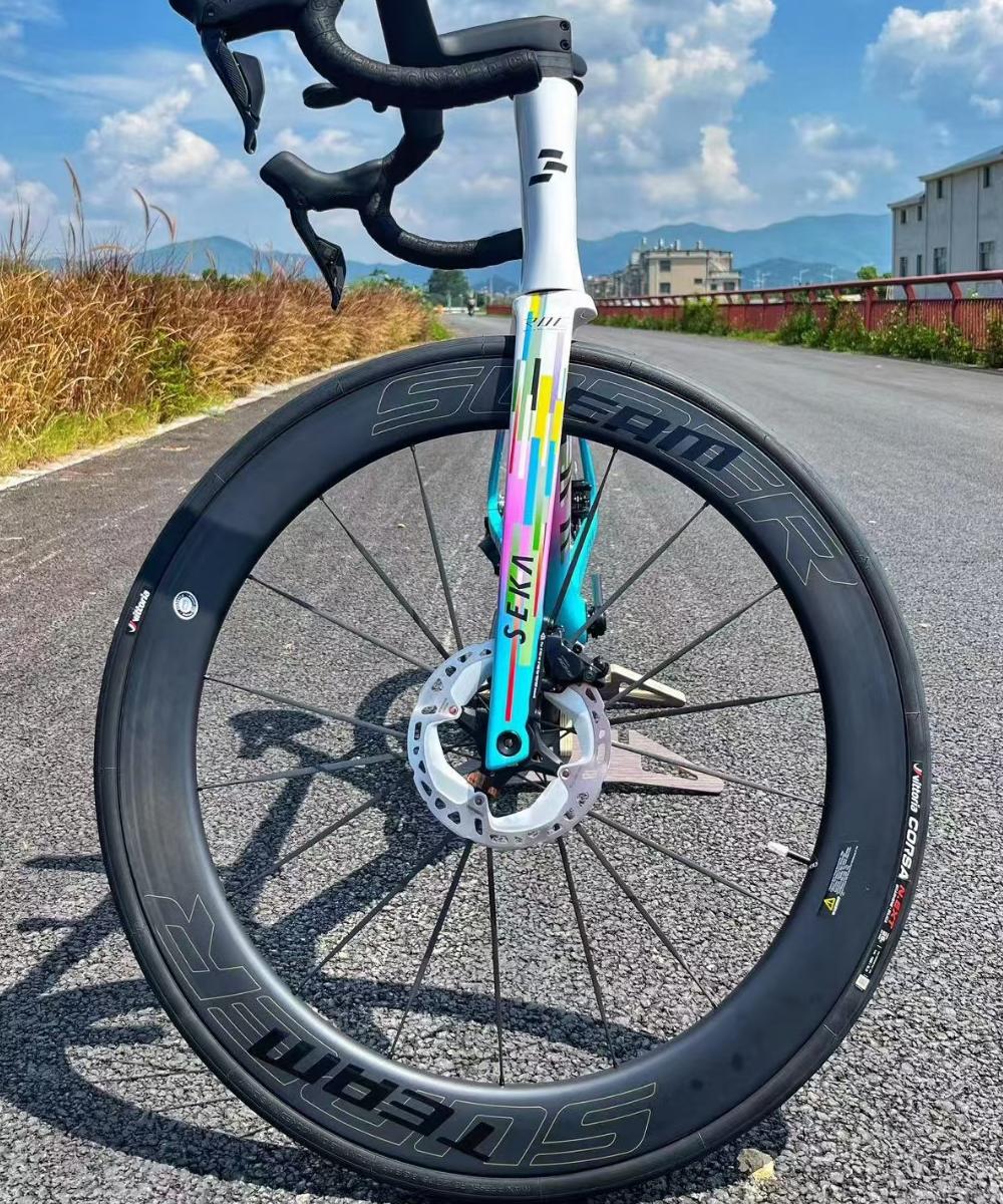
Basic Tools Required
Most alignment checks can be done using simple, widely available tools. A truing stand is helpful but not required. A bike stand, flashlight, feeler gauges, thin paper strips, hex keys, and a ruler or caliper are sufficient for most home measurements.
Optional tools include a rotor truing gauge or a dial indicator for more precise readings.
Initial Visual Alignment Check
Secure the bike in a stand and spin the wheel freely. Observe the rotor passing through the caliper slot while shining a light from behind the caliper. Look for visible side-to-side rotor deviation or uneven gaps between rotor and pads.
A consistent gap on both sides indicates good baseline alignment, even if the clearance is small.
Paper Gap Measurement Method
Insert thin paper strips or feeler gauges between the rotor and each pad without applying the brake. Measure the maximum thickness that fits on both sides.
If one side consistently accepts significantly less thickness, the caliper is likely offset relative to the rotor. Documenting these values provides a reference for future adjustments.
Rotor Runout Assessment
Spin the wheel slowly and observe where the rotor comes closest to each pad. Mark the tightest point using a non-permanent marker. This identifies rotor runout rather than caliper misalignment.
Minor runout within tolerance can be acceptable, especially on thin road rotors, but excessive deviation will reduce usable alignment margin.
Caliper Float and Centering Test
Loosen the caliper mounting bolts slightly and apply the brake lever firmly to center the caliper over the rotor. While holding the lever, retighten the bolts to specification.
Recheck the pad gaps using paper or feeler gauges. If the alignment improves, the issue was caliper positioning rather than tolerance limits.
Rotor Offset Evaluation
Measure the distance from the rotor braking surface to the hub flange or lockring face using a caliper. Compare this value against known standards or another wheelset.
Rotor offset inconsistencies can push alignment outside tolerance even when calipers are correctly centered.
Dynamic Alignment Test
Apply the brake lightly while spinning the wheel and listen for intermittent contact. Then apply progressively harder braking force and observe whether rubbing increases.
Rubbing that appears only under load may indicate flex in the caliper, adapter, or frame rather than static misalignment.
Quantifying Acceptable Tolerance at Home
While manufacturers rarely publish exact tolerances, a practical home benchmark is that the rotor should spin freely with no audible rub and maintain at least a thin paper gap on both sides at the tightest point.
If alignment leaves no margin for wheel flex or heat expansion, the system is functionally at its tolerance limit.
Common Causes of Reduced Alignment Tolerance
Worn pads, uneven pad retraction, warped rotors, misaligned mounting faces, and adapter stack-up errors all reduce usable tolerance. Hub bearing play and axle preload issues can also affect alignment consistency.
Always verify axle tightness and hub condition before adjusting calipers.
Tracking Alignment Over Time
Recording gap measurements and rotor behavior after setup helps identify gradual changes caused by pad wear or rotor deformation. This is especially useful for editorial testing or long-term component reviews.
Consistency across multiple wheel installations indicates a stable frame and caliper interface.
Conclusion
Measuring disc brake alignment tolerance at home is achievable with simple tools and careful observation. By combining visual checks, gap measurements, and dynamic tests, riders and mechanics can understand how close a system operates to its limits. This approach allows more accurate diagnosis of brake noise, drag, and performance issues without relying on professional workshop equipment.